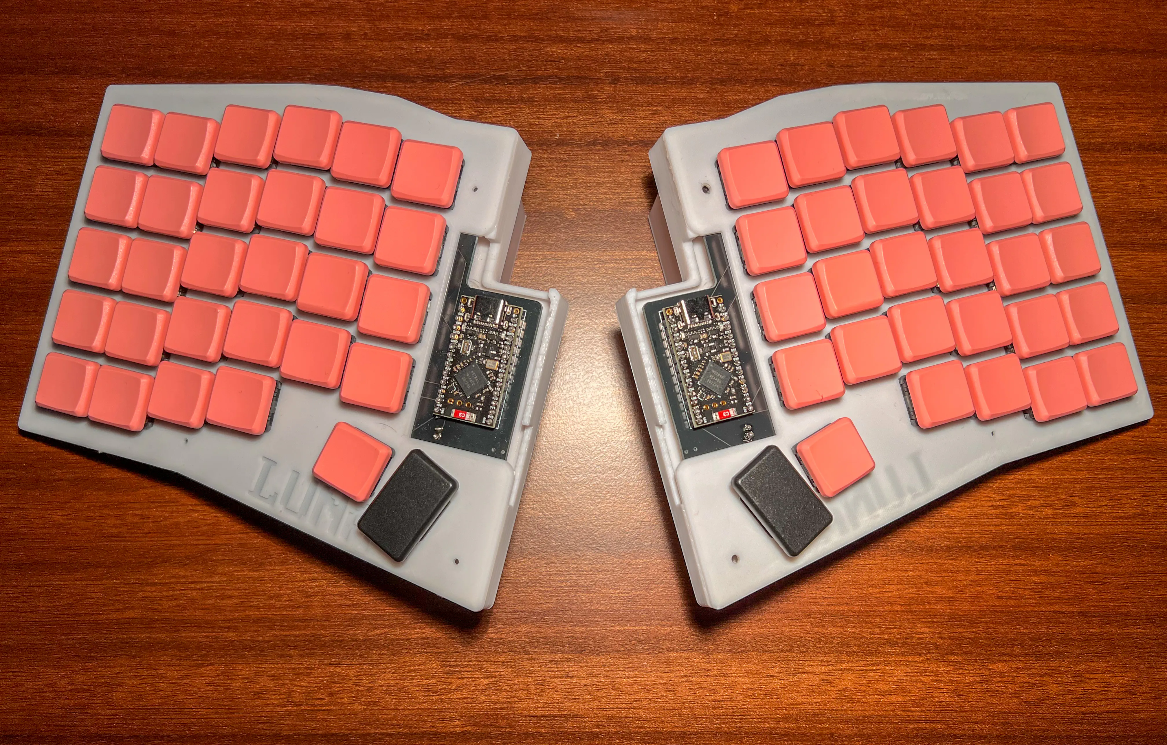
I built another keyboard. This time I've gone a little crazy
Intro
It’s been a while since I last posted— April, to be exact. While I could give you plenty of reasons why I just couldn’t write any more posts I got to be honest. I just wasn’t feeling like it. I have countless ideas written down and around 3 half finished posts. But I was just not feeling it. But since you’re reading this, I got good news. I am back, to enlighten your mood with one of my little passion projects I’ve been working on, non stop, for about 2 weeks. Yes, you read the title correctly. I built my very own ergonomic split keyboard. And I am here to spill some tea about that process.
The Idea
The idea wasn’t new to me. You just need to take a look at my post history - which isn’t that long, I know that myself - and see that I like custom build keyboards. And I still do enjoy this very expensive hobby. But I figured that I’d use only one keyboard anyway. No use in having so many of them anyway. Well that’s what I though until I found this video of Christian Selig. I was caught by the idea of completely designing my own custom keyboard completely from scratch. I mean I am the one who runs a custom DWM desktop that I navigate trough with my custom keyboard. Going even a step deeper and completely doing it myself was just great.
And yes, I used the same tools that Christian used as well. But I don’t think this is a bad thing at all. That’s what they are for, making life easier and the learning process more fun. But I think I don’t have to justify myself anyway so let’s start into the process of building my own custom keyboard I called “Luna”.
Designing
This part is probably the hardest part. I had to learn so many new tools and AI really wasn’t helping either. It’s either that this is a very specific topic, that is still very unknown to mankind or a bit too new. I don’t know yet. But considering the lack of “Online Tutorials” makes me believe it might be the former one. There are however a few guides which I used to get trough this whole process. Specically FlatFootFox’s guide helped me find some leads on which direction I will need to go, when sticking to this process. Another Person that helped was Ben Vallack and the community discords of the tools that I used.
The Tools
The tools I used for designing are:
- Ergogen: For designing the PCB (and a little more)
- KiCAD: For wiring the PCB and getting an STL-File of it
- Blender: For designing the case
- ZMK: For writing the firmware to make the keyboard actually do things, other than catching some dust
I did of course use some online tools as well, and my journey was about as straight as a circle. While I was totally happy with Ergogen, KiCAD and ZMK, I initially wanted to use FreeCAD for designing the Case. Though there was a guy from the hackspace I frequently visit, that taught me how FreeCAD works - around 5 months ago, when I wanted to design a case for my Raspi - I pretty much forgot everything about it again. I tried for roughly an hour and then gave up, hoping Fusion360 was the tool that would redeem me. And while I can imagine it might have been the tool, the lack of Linux support stood in the way between me and Fusion360. Running it it wine wasn’t really working, because I needed to log in through a browser window which wouldn’t open. And my GPU-Passthrough VM - A topic which I wanted to write a post about, but you know. Didn’t - wasn’t really handling it as well. So I looked for an Open Source alternative and found Blender. Blender is a tool I used to work with, back when I did 3D Dubstep intro’s for my YouTube Channel. But that was a long time ago and I didn’t remember anything about it at all.
Getting the hang of it wasn’t too hard, but I don’t want to spoil everything.
Ergogen: Getting started
Ergogen is a neat tool that helps you design the PCB of your dreams, by writing a yaml config. Well kinda, if you know what you are doing. Here are the rough steps what need to happen in Ergogen to get to a functioning PCB.
First, you will need to define a matrix for the keys of your keyboard. Why you ask? Well, a microcontroller has a limited number of pins, so hardwiring every single key to a pin won’t work. Therefore some smart people came up with the idea of a matrix based design which would decrease the number of needed GPIO-ports drastically. It works like addressation in DRAM or on a chessboard if you will. Having done that, you’re greeted with a bunch of options what to exactly do with the matrix now. Remove certain keys, move them around, etc. Once you fiddled around enough and have a good looking design you can go into the next step.
Designing the outline. The outline is basically how the shape of your PCB will look like in the end. You will need to fit every key you defined earlier onto the PCB and make sure to have some spare room for all the other parts you will be using as well, such as a microcontroller. Shape also matters, so you might want to spice it up a little, get in some nice edges and take your time. In retrospective, giving it another day or two would have spared me some issues later on, but I forgot to skill my patience before I was born.
Happy with your outline? Good because we’ll need to also stock it up with all the different components a board like this will need. First - of course - the different spots for the keys you will be using, so you can solder the sockets and diodes on there later. I decided - more or less voluntarily - for choc type key switches. Honestly I just copied that part from the docs and realized afterwards that MX and choc are different switch-types. Well anyway, you’ll also need a place for your microcontroller, battery jack, power switch and reset button. These are all the parts you configure in the PCB/Footprints section. When you’re happy with how it looks you can export your pcb and start KiCAD.
KiCAD
This is a great tool. Very intuitive and I am sure extremely useful for people who know their way around electrical engineering. I am a computer scientist so this is a world I am the stranger in. All I knew was to wire up the different components together. Luckily it was indicated which piece needs to be connected to which other piece. So it was kind of like color by numbers with the exception of physical boundaries. You couldn’t just simply cross two wires, which is why you need the find a way to make these - in my case - 200+ connections without crossing once! It took me a few tries to finally achieve this and so I placed my order for the PCB’s to be manufactured. I couldn’t find a cheap european company so I hit up good ol’ China for this task. Paying double because of heave shipping costs. Around the time where I received the notification that my PCB has been manufactured and shipped I noticed that little yellow circle icon, which indicates, that I could pull the wire to the other side. That basically means, that I had a way to actually cross the wire paths. The company that made the PCB’s probably was probably devastated by my horrible wiring job and I am sorry for every headache I’ve caused them.
Blender - or FreeCAD?
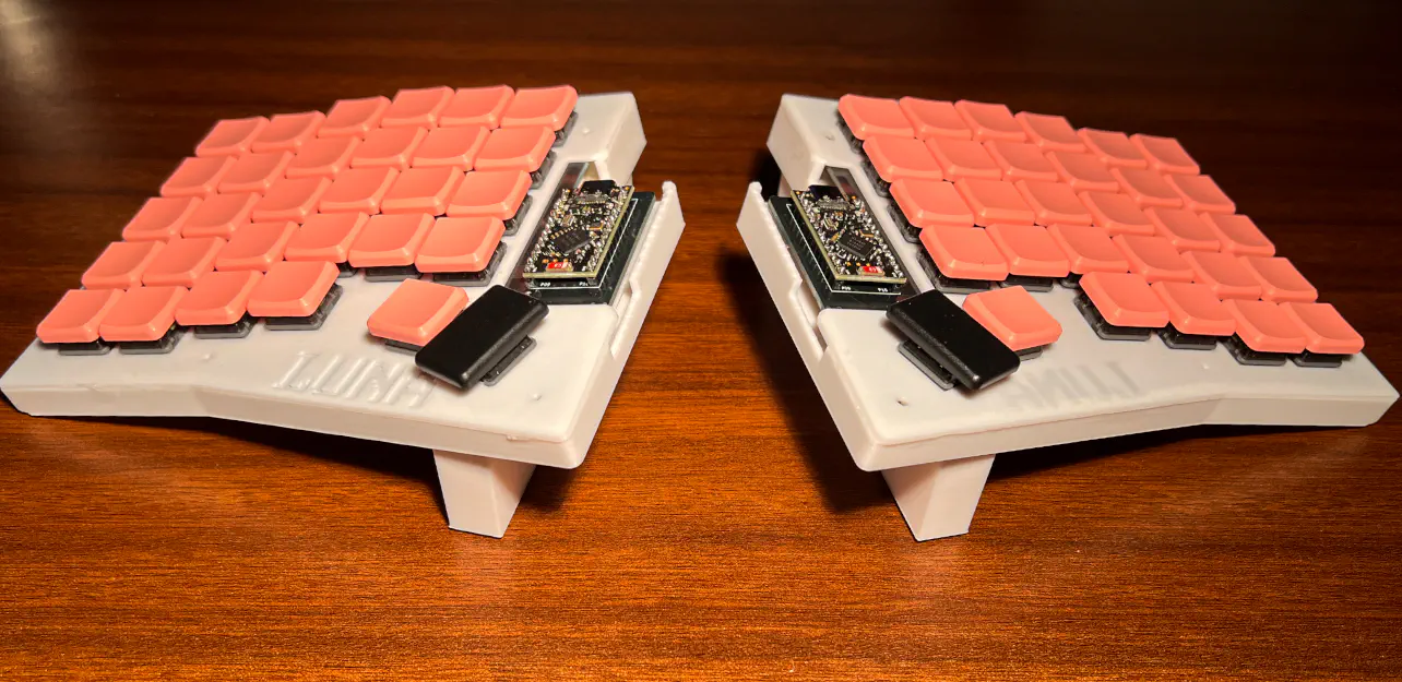
I already told you about my struggles getting the right tool set up, so I could design a case for my so beloved keyboard. And while I used blender, I barely touched the surface of the wide variety of tools blender had to offer. All I did was basically apply the ‘bool-transformation’ to get the holes I needed. For the bottom part I actually utilized the ‘outlines’ of Ergogen, by creating a slightly bigger variant of my actual outline. Then I subtracted this one, with the original one and extruded it to roughly 2,5 cm. This was going to be the outer wall. Then I added the original PCB to that wall and what I had was a good looking bottom half of my case. It missed holes for screws and the different connectors, but that was a job for blender. I also took the original PCB outline, subtracted it from the keys matrix which in return left me with the plate.
Putting these two into blender - and a model of the finished PCB just so I have a rough idea what I am working with - I got to designing. I started by adding a mechanism so I could hold the PCB at a 2,436° in place. (I spent quite some time on this. While writing this, I still remember the number.) Then I made some place for the microcontroller and the switches and put it all together. Right before I was done I thought the ability to angle the board would be great. So I came up with this lego like design, angeling it up to 14°. If the print goes right and the parts connect, this lets me decide if I want to have my board angeled or not. I exported them all, sliced them to see if everything was good and asked a friend to print it for me.
ZMK
Getting the firmware ready was a bit tricky. There is a very thorough documentation but finding all the right things that I would actually need for my specific case proved quite difficult. Everytime I tried using Google or AI it just referred me to paged I’ve already read. The main thing that helped me get through this was the very helpful community. I joined the ZMK discord and asked my questions, which were answered pretty quickly. This enabled me to get to a compilable software in about 2 days. The lack of an LSP had me farm a lot of commits for my github profile as syntax issues only came up, when I pushed the changes. This led to me fixing one error at a time until I had these errors sorted out. Well at least until I reached a point where I wasn’t struggling with syntactical errors anymore, but rather compilation errors that I didn’t really understand. It took me a few hours and a very nice person on the ZMK discord to check, what kind of controller I selected, when I set up the ZMK environment. You see, I am a cheapskate. I didn’t plan on buying two ’nice!nano v2’ because they were kind of exceeding my spending limit (not that some stupid mistakes of mine already exceeded it by 200% but more on that later) so I decided to go with NRF52840 Pro Micro controller. They were cheap, labeled the same as the ’nice!nano v2’. Only downside was the china shipping but that was expendable. Why I am telling you this? Well I looked into it and at the time of setup I was greeted with a ‘NRF52840 Micro’ chip. At first I was very happy that the controller I was using, was actually supported. Spoiler: It wasn’t. These are different kind of controllers, which at that time I didn’t realize. After I changed the controller to the ’nice!nano v2’ it finally compiled and was ready to download.
While I was able to compile, I couldn’t test if it would actually worked. So I just hoped for the best.
Assembly
Well first of all, you have to know that I am a computer scientist. All I do is just apply abstracted concepts that move 1’s and 0’s around until the hardware I solely rely on does what I want it to do. Therefore I was completely inexperienced, going into this. While I was waiting for the parts to arrive - including a soldering iron which also costs me more than I wanted to initially spend - I was pretty bored. This has been a project that I really put everything into, so the downtimes were kind of boring. I probably exceeded some API Rate Limits with the amount of refreshing I did, on my package tracking site. But hey, eventually they arrived. And when they did, I did not hesitate and got right into it.
Soldering
I feel like it’s the same story for everyone, soldering the first time in their lives. After all it is a quite daunting task, until you get the hang of it. It was the same story with me. The first tries of diodes looked horrible and I think I had to desolder more, than do actual soldering. But when you have to solder over 128 components, you’ll get into it eventually. I think after the first 30 diodes I pretty much knew what I was doing and got into a pretty fast pace. Of course I made some mistakes and it definitely doesn’t look perfect, but for me it only has to work in the end.
You cannot imagine how badly I would like to tell you that’s the end of the story, but as you can imagine. It isn’t. My soldering experience went pretty okay-ish. The diodes and hot swap sockets came first. And I already had the PCB’s, so I began to solder these parts first for both boards which took me roughly 2 days. I also soldered the battery jack and power switch onto both boards. Then I had one painful day of waiting ahead of me to wait for the microcontrollers to arrive. I was very excided and when they came I jumped right into it and soldered them on. Excided as I was I ran up to my computer, plugged the first one in and shortened the RST and GDN pins to cause a reset instruction. It worked, mounted to my PC and I could install the first firmware. I was really feeling it until I plugged the second one in and noticed that the red light, that was blinking on the other controller, didn’t light up. I feared I did something wrong with my soldering, but then it came to me that my soldering had nothing to do with the behaviour of the microcontroller. Well I reset this one again in hopes of it mounting, but I was disappointed. The controller, as I found out had no bootloader installed.
This was scary as I used regular header pins in the process and desoldering wouldn’t be easy. I tried for two days. Using a solder socker and one of these desoldering wires but the controller didn’t move an inch. I looked at what else I could do, when I saw that I could just cut the pins and remove the pins by reheating the solder. And so I went to my local hardware store and bought thin pliers for 25 EUROS. FOR PLIERS. I was able to remove the controller and these are the results.
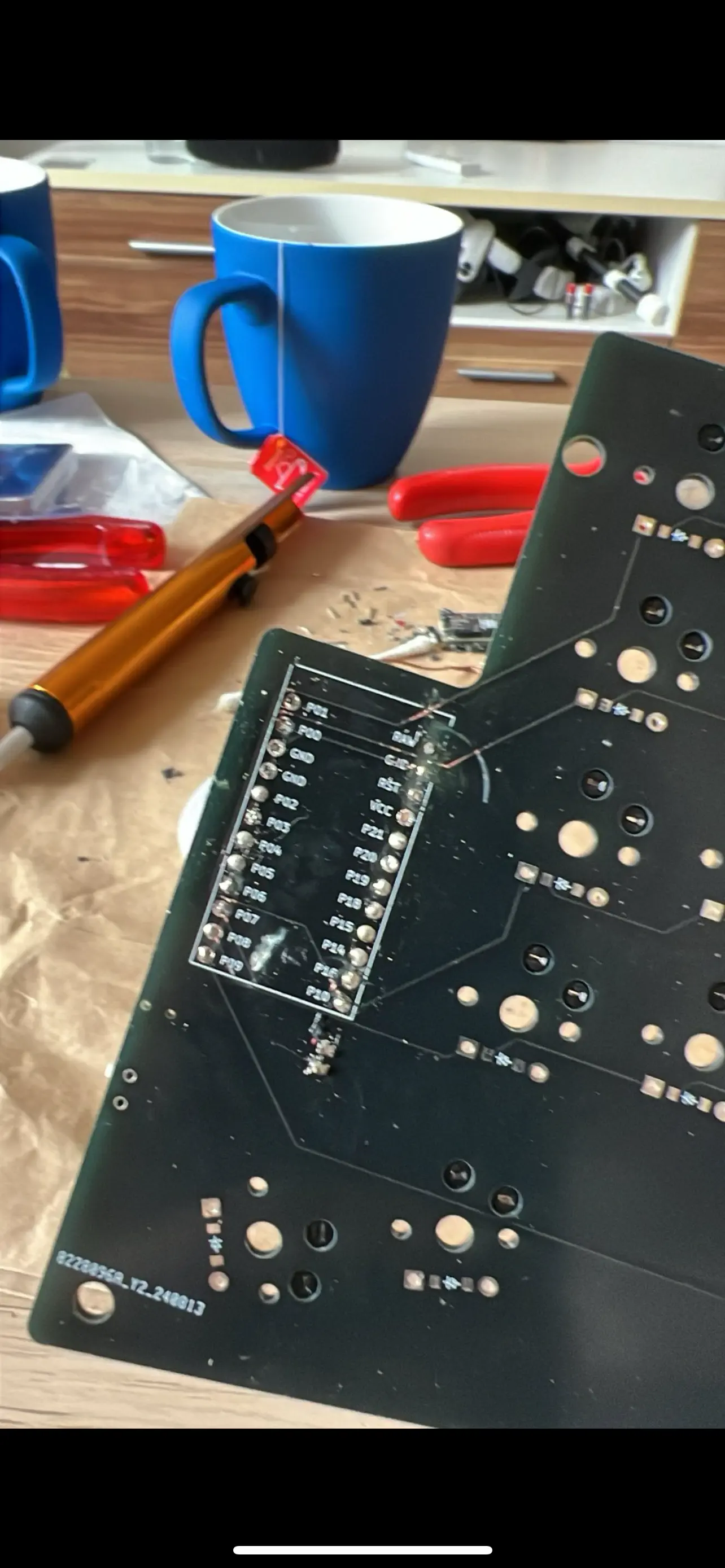
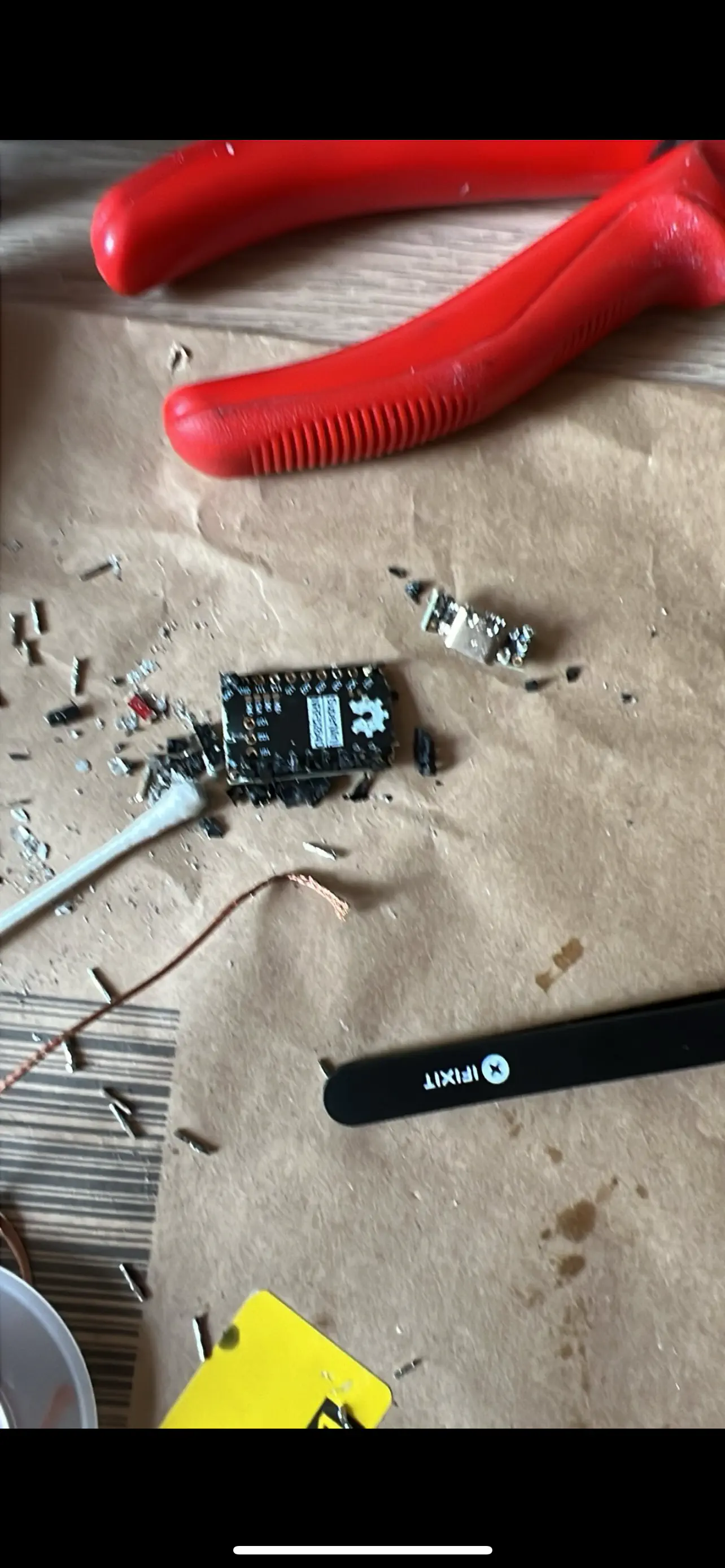
Yes, I damaged my board. Though I do have 5 PCB’s for each side, I didn’t have any spare hot swap sockets or diodes, which is why I had to order another 30 of them, again exceeding my spending limit. On the same note I had to get a new microcontoller as well. Keep in mind that the China shipment took around 12 days so waiting for a new one to arrive would be soul crushing. So I looked up amazon and found the same controller, for double of what I paid from the initial order. I took the sacrifice.
While I was waiting for another weekend to pass by, I focudes on the left side of the keyboard, which should technically work now. So I assembled the parts needed together, turned it on and to my surprise the keyboard showed
as a bluetooth device on my phone. I connected to it and. Well, I could type. But the keys were not correct at all. So I knew I had to adjust the firmware. I did exactly that, flashed it and almost everything worked. Except 3 keys.
At this stage I was pretty worried. A lot of time and money went into this. I didn’t know what I would do if I would’ve hit a point where I just couldn’t fix these issues anymore.
Scared but ambitionate, I turned around the board and looked at my soldering job. While it looked mostly fine, I couldn’t trust it. I knew that I didn’t have spare parts- WAIT I do have spare parts on my old, broken board.
I desoldered around 8 sockets until I had 3, that I didn’t destroy during the desoldering process and swapped them out.
To my surprice I was able to hit the 2 key. Unfortunately I still had no luck with the thumb keys.
You see, back when I was designing the board in Ergogen, I separated the thumb cluster from the origin matrix so I could wire the both keys into their own GPIO-Port. I thought that this was easier and SPOILER. I was wrong. Ergogen couldn’t handle the wiring, which left me with a missing connection to GND. That means that I could swap as many sockets I want, without a working circuit I was doing nothing. The ZMK’s discord people helped me out here and suggested I wired them manually. So I did exactly that and voilà. I had fully functioning left side of the keyboard.
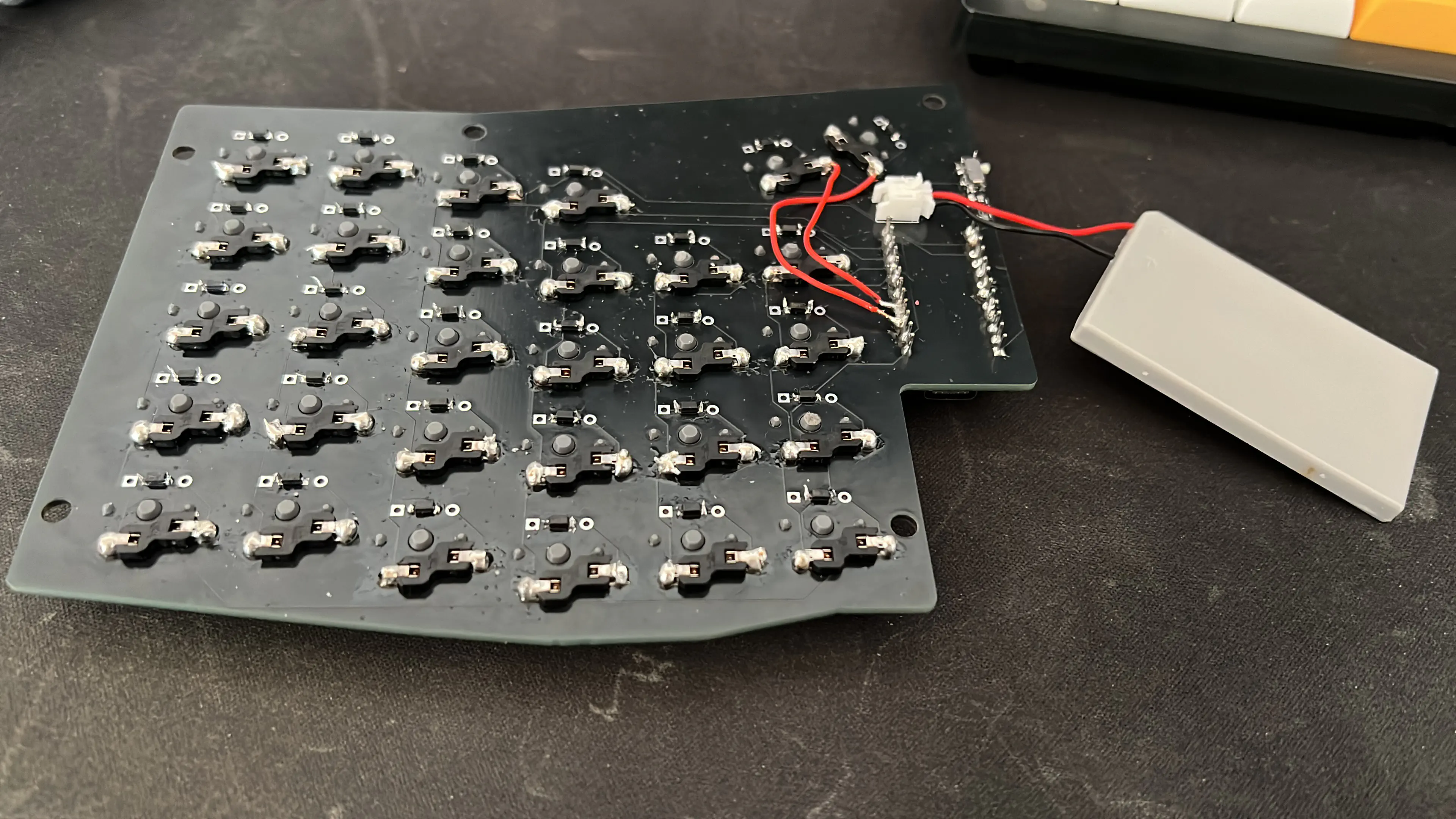
I got to a point where I exactly knew what needed to be done for the right site and when the parts came I was fairly quick, soldering and wiring everything together. Another dead key, same working fix by swapping the sockets.
I was almost done. What was missing was the final assembly.
Case
With all the components ready, it was time to bring everything together. Though I have some tools of my own, I decided to tap into my father’s extensive collection because I was lacking screws (Would’ve been good to know that he is lacking the screws I needed as well). After an hour’s drive, I arrived at my parent’s place, eager to see the final product come together. But, as with most things in this project, there were a few hurdles to overcome.
The first issue arose when the battery wires turned out to be too short, preventing the battery from fitting into its designated spot within the case. This wasn’t just a minor inconvenience—it completely halted our progress. We had to extend the cables of both batteries, but lacked the tools you would normally use to properly get the job done. Instead, my father dug out an old soldering iron from his garage, along with some incredibly thick solder compared to the fine 0.8mm solder I had been using. The soldering job was horrible. Thick solder made the work clumsy, and my hands weren’t as steady as they used to be. But, against all odds, the connections held, and the batteries were securely in place.
With the wiring sorted, the rest of the assembly was straightforward.
You didn’t believe me, right? Well of course the mechanism I planned out to screw the case together didn’t work out as expected. At this point I just wanted to get the job done so I did what every reasonable and grown up person would do. Wait, reiterate trough the design-SIKE. I glued it together. Thats it. Plain, simple and prevent me from ever repairing anything without probably breaking the case. But that’s a problem for later me. At least I will have another topic to write about in the future.
Aftermath
Now, after three days of using LUNA, I can confidently say it was all worth it. My typing speed has dropped from around 100 WPM to 60 WPM, but I can feel myself getting faster each day as I adjust to the new key positions and the split design. Despite the initial frustration, I know that in time, I’ll likely surpass my previous typing speeds. The comfort and satisfaction of typing on a keyboard that I built from the ground up is unmatched. I’ve already started thinking about small tweaks and improvements for the next iteration of LUNA. Perhaps I’ll experiment with different key switches, or maybe I’ll refine the case design further. Maybe next time I will not spend 360 Euros on a keyboard which could’ve easily cost me like 150 if I had just known better.